How To Get The Best Results
For most TVs, it isn’t necessary to make any adjustments to the settings to take advantage of a wide color gamut with HDR content. Leave the ‘Color Gamut’ or ‘Color Space’ option to ‘Auto’ for most brands. The Auto setting will automatically adjust the TV’s color gamut to the gamut of the content, so if you’re watching SDR content, the TV will only display SDR colors. However, some TVs also have ‘Native’ settings, where the TV stays on the same HDR color gamut no matter the content. If you’re watching SDR content, it will over-saturate the colors to match an HDR color space, which some people may prefer. You may also need to enable full-bandwidth signals to achieve the best HDR experience possible.
Step 2: Convert Assets to ACEScg
|
|
|
|
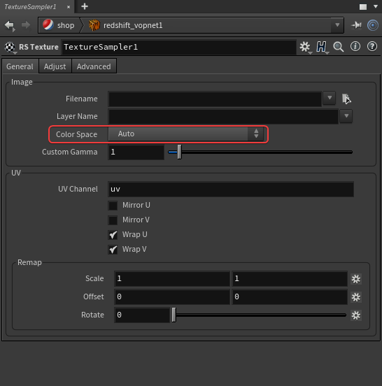
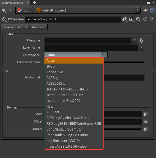
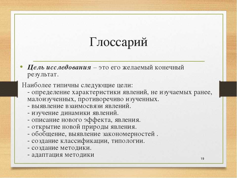
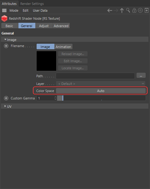
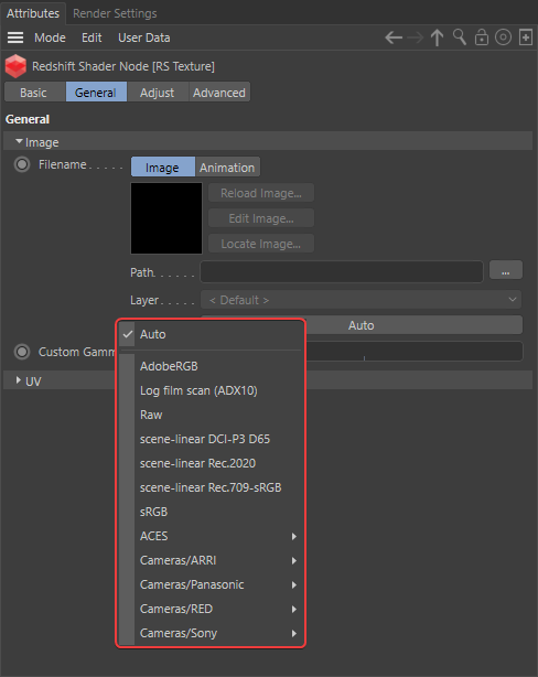
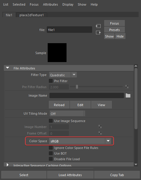
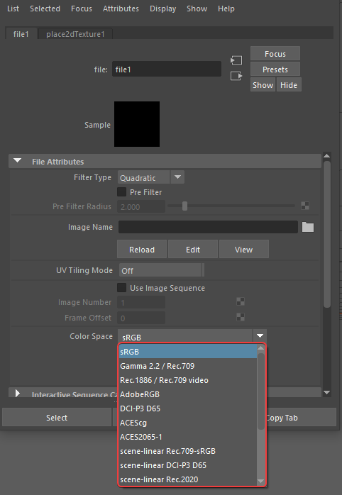
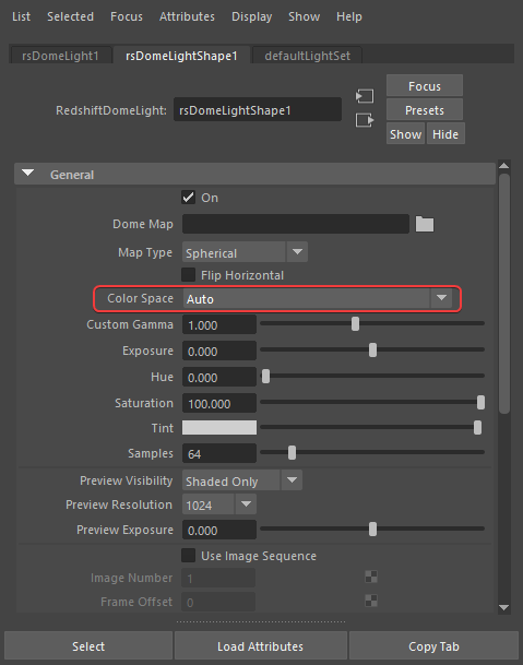
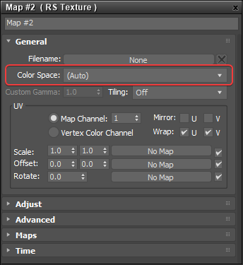
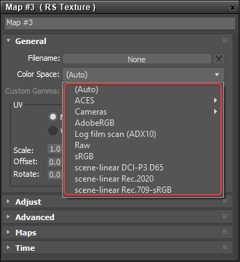
In order for colors to display as expected all source assets must first be converted into the same linear rendering color space, ACEScg by default. This is accomplished by setting the color space correctly for each asset using the color space drop-down menus pictured in the pictures above. These color space parameters serve as a built-in Input Display Transform (IDT) when viewed through the lens of an ACES workflow, the same general mentality as working with ACES renders in composite as described on this page.
Redshift automatically converts native color swatches like diffuse colors, ramp colors, and the Redshift physical sky into the linear rendering color space. Redshift is set up by default to automatically convert any textures used with materials, lights, and dome lights into the rendering color space but there is a chance that it will get this automatic conversion wrong. It’s important to make sure that the color space is set correctly for each asset which is why it can be overridden manually by following these general tips:
- If your asset is for color data
- Examples: diffuse / albedo color, specular/reflection color, dome light texture/backplate
- If you already know what the correct color space is set it to that
- If it’s a JPG / PNG / BMP etc set it to sRGB
-
If it’s an EXR / HDR etc set it to scene-linear Rec.709-sRGB or other appropriate scene-linear color space
- Examples: diffuse / albedo color, specular/reflection color, dome light texture/backplate
- If your asset is for non-color data
- Examples: normal, roughness, metalness, displacement etc
- If you already know what the correct color space is set it to that
- Otherwise set it to Raw
- Examples: normal, roughness, metalness, displacement etc
|
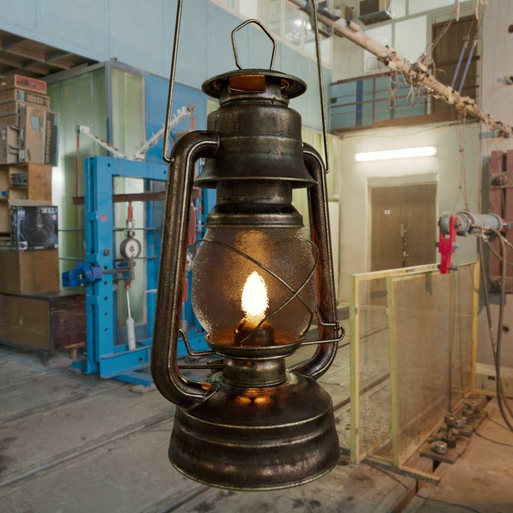
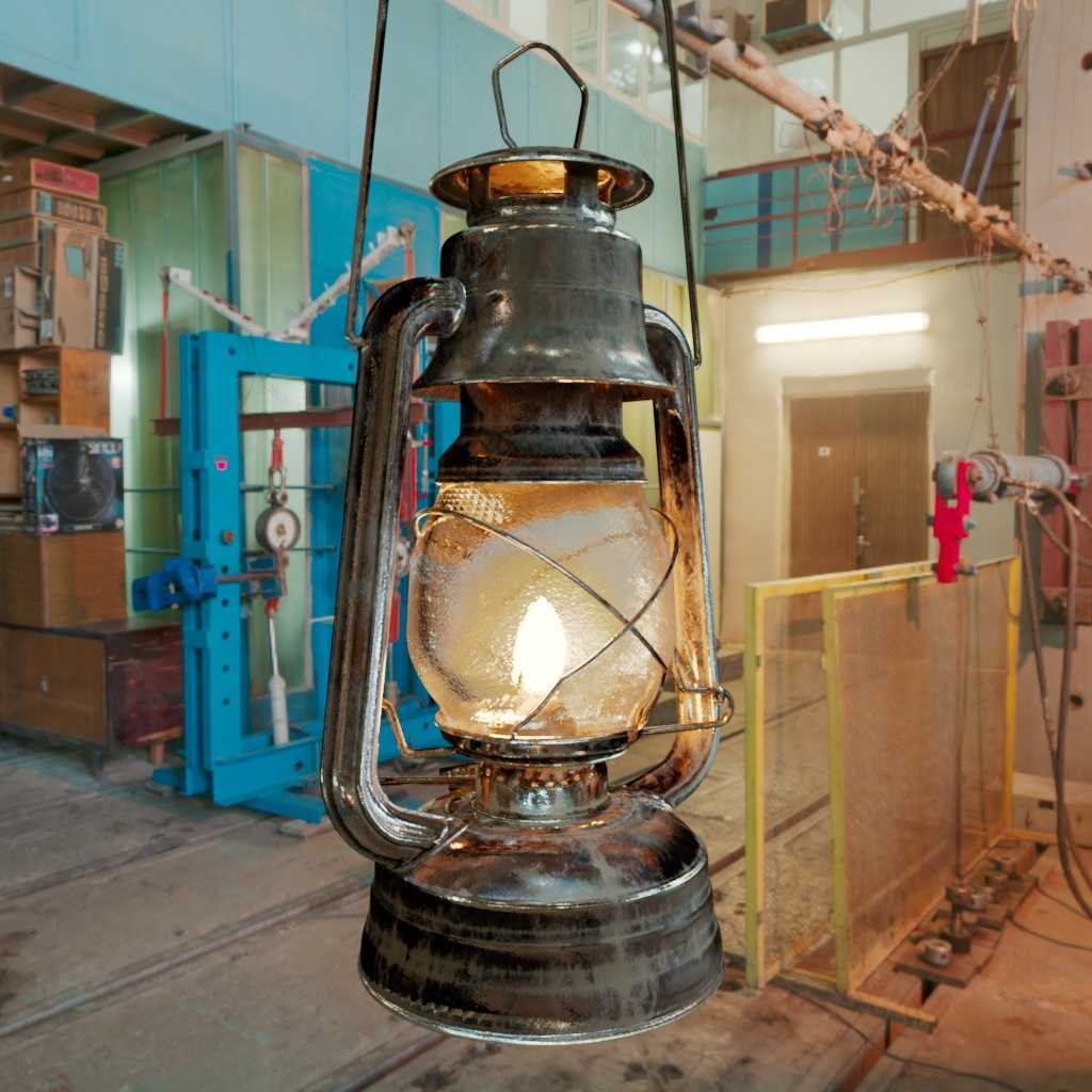
In the example images above the only difference in scene setup is that the color spaces were set up correctly versus incorrectly. The diffuse color texture was set to raw instead of sRGB and all non-color textures were set to «sRGB» instead of the correct color space «Raw.» Setting the color spaces correctly is required in order for renders to look right, in general incorrect color spaces for non-color textures negatively impacts the final result more so than incorrect color spaces for color textures. For example, the result of the normal map in the incorrect example looks fully broken, resulting in jagged unnatural reflections that fall far from achieving the correct result on the glass and in the bottom left of the lantern. Incorrect color spaces for color data like diffuse color and HDRI dome light backplate are more subjective, while still technically incorrect they don’t visually break as drastically. For example, notice that the HDRI in the background becomes too saturated when incorrectly set to color space «raw» instead of «scene-linear Rec.709-sRGB,» this is because it is being incorrectly transformed into the too wide gamut of ACES2065 vs the proper sRGB gamut that the HDRI was originally captured in.
You can download the model, textures and HDRI with the links below to easily recreate the demo scene pictured above. Model and texture credit to Rajil Jose Macatangay at PolyHaven.com HDRI credit to Oliksiy Yakovlyev at PolyHaven.com |
E.G. of use:
For display :
sRGB : is for typical 8bit CRT monitor display, so for web, photo display…
I think Apple use a different profile but I don’t have Apple devices so I can’t say more.
![Как новые форматы ultra hd и 4к совершат цветовую революцию. часть вторая [перевод] • stereo.ru](https://thelawofattraction.ru/wp-content/uploads/d/2/b/d2b57f71f49842ac1052b633a6a6952b.jpeg)


Rec 709 : is for TV/Cinema display
For post prod :
CIE XYZ : In blender with the view set to Log you have the typical washed out picture used by studios before color gradding video footage.
Linear space : That isn’t a color space since colors aren’t defined, it’s the scene referred space, it’s what Blender calculate internally and how light intensity works in real life. It can’t be displayed correctly on a CRT monitor, but keeps all the original datas if the picture is saved in 32bits.
For convertion/compare between different spaces :
CIE LAB : is an absolute color profile, like a reference to calculate all colors even colors that cannot be reproduced in the physical world.
More about the topic :
Ссылки [ править ]
- . МСЭ-R . МСЭ-R . Проверено 10 декабря 2020 .
- Рек. МСЭ-R. BT.709-5 стр. 18, пункты 1.3 и 1.4
- . Информационный дисплей. Архивировано из на 2013-01-12 . Проверено 1 января 2013 .
- Сюй Янь; Ли Янь; Ли Гуйлин (май 2009 г.). . 2009 13-й Международный симпозиум по бытовой электронике IEEE: 141–143. DOI .
- ^ . www.tftcentral.co.uk . Проверено 5 февраля 2021 .
- . Проверено 16 января 2021 .
- . www.itu.int . Проверено 16 января 2021 .
- . www.itu.int . Проверено 16 января 2021 .
- .
- Пойнтон, Чарльз (2012). Цифровое видео и алгоритмы и интерфейсы HD . Берлингтон, Массачусетс: Эльзевир / Морган Кауфманн. п. 321. ISBN. 978-0-12-391926-7.
- Рек. МСЭ-R. BT.709-6 стр. 3 сноска 1
- Рек. МСЭ-R. BT.601-5, 1995
- . Blackmagic Designs . Проверено 10 декабря 2020 .
Answer
With that in mind, sRGB, Rec709… have differents 1., 2., and 3. They are for different purpose and it’s the answer to your question, you need to choose the one corresponding to your need
In Blender with the default config you have Display device that defines the white point (1.) and the primaries (2.), the view that defines the transfer curve (3.) and you have the look that is a creative transformation of the image, contrast or color tint.
Color profils are applied at the verry end of the chain, so juste before displaying the image or when saving it.
It means that all the compositor transformations you make are applied on a linear image, so all datas preserved but when saved, the image lost information if non 32bits linear.
So exept for some cases, e.g. basic drawing without light interaction, it’s always better to use filmic to view your viewport, even if you save it in linear 32bits at the end.
With filmic what you see correspond to how light intensity works in real life, it’s not the case in sRGB / Default setup.
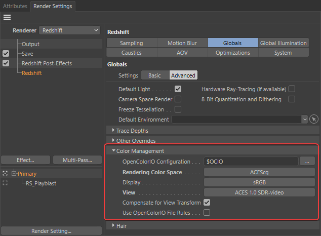
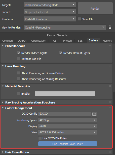
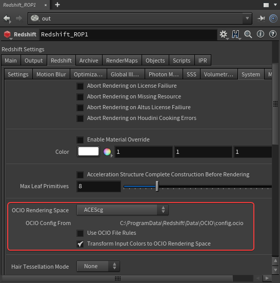
Step 1: Redshift Color Management Setup
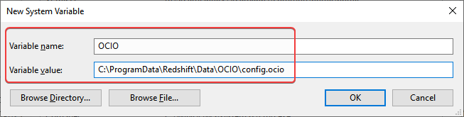
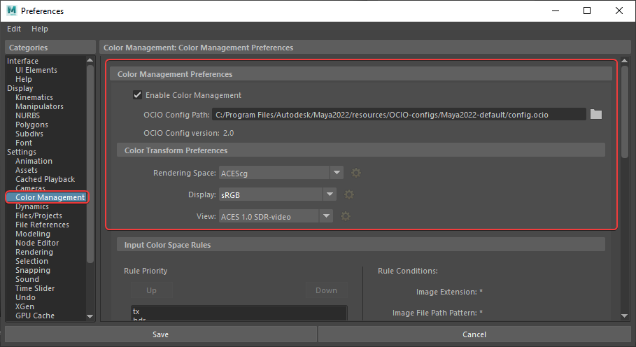
Before working in ACES an OpenColorIO configuration file must be set in the Color Management section of the Redshift Globals render settings. By default Redshift is set up to use the OCIO file path established by your computer’s environment variable, if no OCIO environment variable is established then Redshift will default to the custom OCIO ACES configuration that Redshift ships with. This custom Redshift ACES config is pared down and it contains commonly used input and render color spaces (including ACEScg), as well as some output display transforms. Once an OCIO configuration file is properly specified a rendering color space can be chosen, ACEScg by default.
|
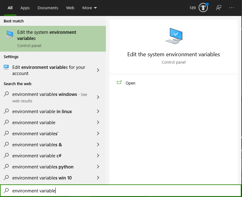
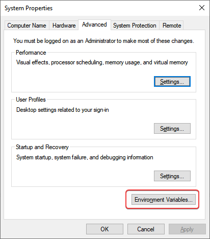
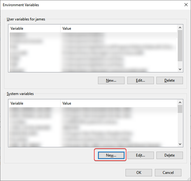
An environment variable is a dynamically-named value that is established at the system level. In practice an environment variable is queried by programs for a custom value specific to that system. For OCIO this comes in the form of an environment variable called $OCIO which corresponds to the file path of your system’s OCIO config. In practice this tells your OCIO relevant software where on your system it should be pulling your OCIO config from and makes it easy to use the same config file across all of your software and through the various stages of production without manually setting up each piece of software. Click below to learn how to set up an environment variable for your system.
|
After the rendering color space is specified you must select a display transform that matches the display you are working on to properly preview the renders. If you are using an sRGB monitor then you would use the default sRGB display transform. In addition a View transform can be selected to tone map the render to your liking, by default Redshift uses the ACES 1.0 SDR-video view transform which has some nice filmic tone mapping.


![Как новые форматы ultra hd и 4к совершат цветовую революцию. часть вторая [перевод]](https://thelawofattraction.ru/wp-content/uploads/6/a/4/6a4d76537d09d4bb8cc782c9fc260eba.jpeg)
Redshift ships preconfigured for the most common ACES workflow but if yours is not setup try using the following settings:
|
|
|
|
Custom OCIO Config
If you would like to use your own custom OCIO config instead it’s as simple as changing the OCIO configuration path in the Redshift Color Management settings to your own config file.
The OCIO config that comes with Redshift is lightweight, if you have the need for more IDTs and ODTs you can download the latest ACES config file released here, save it somewhere on your hard drive and then set its location as the OCIO config path in Redshift or set its path in your own .
Standards conversion
Conversion between different standards of video frame rates and color encoding has always been a challenge for content producers distributing through regions with different standards and requirements. While BT.709 has eased the compatibility issue in terms of the consumer and television set manufacturer, broadcast facilities still use a particular frame rate based on region, such as 29.97 in North America, or 25 in Europe meaning that broadcast content still requires at least frame rate conversion.
Converting standard definition
The vast legacy library of standard definition programs and content presents further challenges. NTSC, PAL, and SECAM are all interlaced formats in a 4:3 aspect ratio, and at a relatively low resolution. Scaling them up to HD resolution with a 16:9 aspect ratio presents a number of challenges.
First is the potential for distracting motion artifacts due to interlaced video content. The solution is to either up-convert only to an interlaced BT.709 format at the same field rate, and scale the fields independently, or use motion processing to remove the inter-field motion and deinterlace, creating progressive frames. In the latter case, motion processing can introduce artifacts and can be slow to process.
Second is the issue of accommodating the SD 4:3 aspect ratio into the HD 16:9 frame. Cropping the top and/or bottom of the standard definition frame may or may not work, depending on if the composition allows it and if there are graphics or titles that would be cut off. Alternately, pillar-boxing can show the entire 4:3 image by leaving black borders on the left and right. Sometimes this black is filled with a stretched and blurred form of the image.
In addition, the SMTPE C RGB primaries used in North American standard definition are different than those of BT.709 (SMTPE C is commonly referred to as NTSC, however it is a different set of primaries and a different white point than the 1953 NTSC). The red and blue primaries for PAL and SECAM are the same as BT.709, with a change in the green primary. Converting the image precisely requires a LUT (lookup table) or a color managed workflow to convert the colors to the new colorspace. However in practice this is often ignored, except in mpv, because even if the player is color managed (most of them are not, including VLC), it can only see BT.709 or BT.2020 primaries only.
Luma coefficients
When encoding Y’CBCR video, BT.709 creates gamma-encoded luma (Y’) using matrix coefficients 0.2126, 0.7152, and 0.0722 (together they add to 1). BT.709-1 used slightly different 0.2125, 0.7154, 0.0721 (changed to standard ones in BT.709-2). Although worldwide agreement on a single R’G’B’ system was achieved with Rec. 709, adoption of different luma coefficients (as those are derived from primaries and white point) for Y’CBCR requires the use of different luma-chroma decoding for standard definition and high definition.
Conversion software and hardware
These problems can be handled with video processing software which can be slow, or hardware solutions which allow for realtime conversion, and often with quality improvements.
Film retransfer
A more ideal solution is to go back to original film elements for projects that originated on film. Due to the legacy issues of international distribution, many television programs that shot on film used a traditional negative cutting process, and then had a single film master that could be telecined for different formats. These projects can re-telecine their cut negative masters to a BT.709 master at a reasonable cost, and gain the benefit of the full resolution of film.
On the other hand for projects that originated on film, but completed their online master using video online methods would need to re-telecine the individual needed film takes and then re-assemble, a significantly greater amount of labor and machine time is required in this case, versus a telecine for a conformed negative. In this case, to enjoy the benefits of the film original would entail much higher costs to conform the film originals to a new HD master.
Monitoring standard and gamma
The first thing to make clear is that Rec. 709 is (subject to some argument about how it’s written versus how it’s actually used) a standard for monitors, not for cameras, although in practice this can be a more-or-less equivalent situation. We can quite correctly refer to a Rec. 709 camera as a shorthand for one designed to drive Rec. 709 displays. This implies the camera will output a signal where the number of real-world photons hitting the sensor is encoded, so it’ll look reasonable when the display decodes it back into photons again. The relationship between encoded numbers and the amount of light coming out of the display is not straightforward, for complicated historical reasons, and if it isn’t right, the image will look too contrasty, too flat, to dark or too bright.
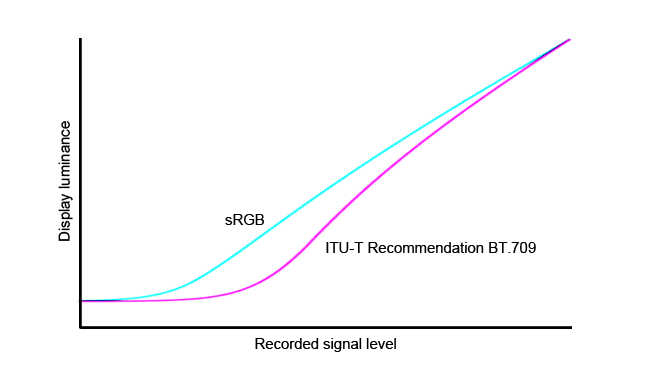 Rec. 709 gamma curve, shown here in comparison to the sRGB curve used on computers.
For the record, Rec. 709 defines a gamma of 2.2, which is a complicated way of saying that the actual stored brightness value in, say, a video file is based on the amount of light that hit the sensor raised to the reciprocal of 2.2, give or take some fudging in the darkest parts of the signal that’s designed to hide noise. The number is chosen because the standard is written from the perspective of display; the power will be raised to the value 2.2, darkening it, when it hits the monitor, so we must brighten the image when we store it. The reciprocal of 2.2 is equal to one divided by 2.2 (roughly 0.45). This figure was chosen because a cathode ray tube display has a relationship between input power and brightness roughly approximated by raising the input power to 2.2, which goes to show how old a standard this is. Gamma encoding is necessary no matter what, because our eyes are not linear. We don’t see a doubling of photon count as a doubling in brightness, so we would make very inefficient use of data space if we stored linear data (as we’ve discussed in other articles), but it was also a big part of how TV worked back in the days of CRT displays. Modern TFT displays have been engineered to emulate the same behaviour so everything works out nicely.
Common OCIO color spaces and their purpose
|